
Copyright (C) 2011 KABtronics
Nixie-Transistor Clock
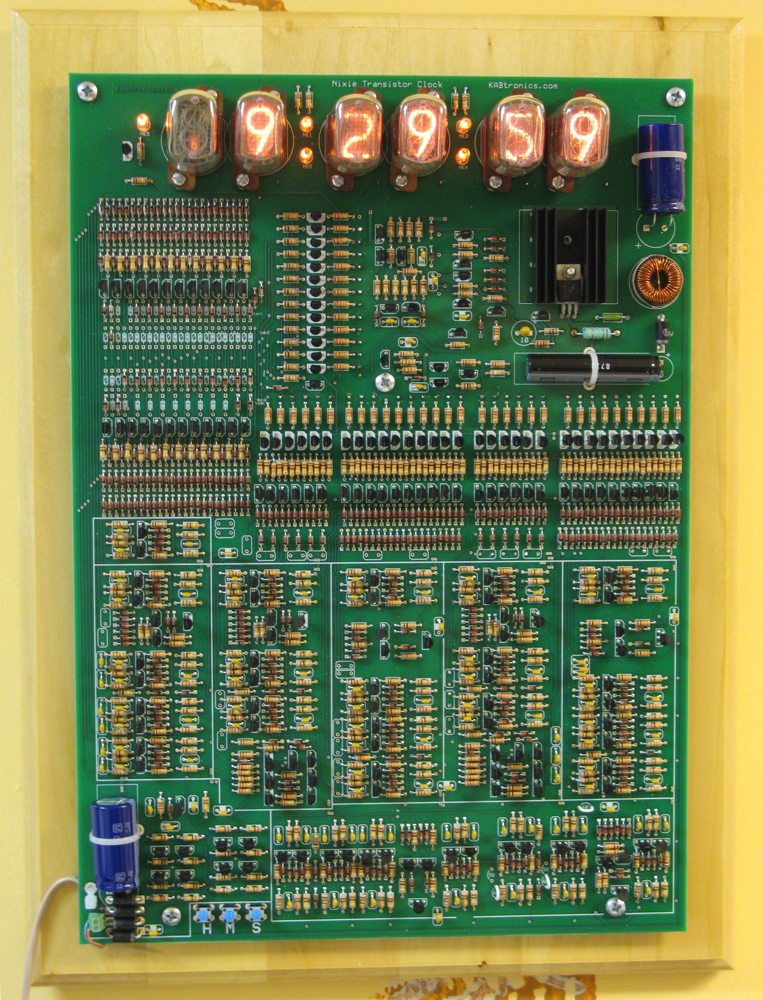
This is a Nixie Tube display version of the Transistor Clock. It uses only discrete components, no integrated circuits.
This
kit is for advanced, experienced builders. You need to have an oscilloscope, a voltmeter, and an inquisitve mind tempered with
patience.
Read the manual on the details page before ordering to understand the level of the commitment you are making.
You may want to consider building the Transistor Clock first if you have doubts, that is a much more forgiving kit.
Features:
- 50 or 60 Hz jumper settings
- Seconds Hold switch
- 12 or 24 Hour decoding
- Display turn-off by the hour
This clock runs on 12 Volts AC, 50 or 60Hz and develops 180 Volts. The kit includes;
- 215 Transistors
- 518 Diodes
- 472 Resistors
- 101 Capacitors
- 10" x 14" Printed Circuit Board with silk screen symbols indicating component locations
- Nixie Tubes, Nixie sockets, solder, solder-wick, misc other parts, printed assembly manual
- Wall Transformer for 120VAC (Us Mains)
See the Details page and photo page for more info.